| Home | Energy | Nuclear | Electricity | Climate Change | Lighting Control | Contacts | Links |
|---|
INTRODUCTION:
This web page is intended to introduce Fast Neutron Reactor (FNR) issues to individuals who have a basic science education but who know little or nothing about FNRs.
IMPORTANCE OF FNRs:
FNRs provide the only non-CO2 emitting technology that can sustainably and economically fully displace fossil fuels. FNRs, with low pressure coolants and triple radio isotope isolation, can be safely sited within major cities for supply of electricity, industrial heat and buried network distributed winter comfort heat.
FNRs operate by converting abundant fertile isotopes such as U-238 and Th-232 into fissile isotopes such as Pu-239 and U-233 faster than the fissile inventory is consumed. With suitable fuel recycling FNRs can enlarge the natural fissile isotope supply more than one hundred fold. The 300 MWe/1000 MWt FNR detailed on this web site is intended for urban installation. Each such reactor will meet all the power and energy requirements of about 100,000 people.
As compared to other nuclear power tecnologies, the FNR fuel cycle reduces the long lived nuclear waste disposal problem by more than 100 fold.
An important feature of FNRs is that they operate at higher temperatures than water cooled reactors. A sodium cooled FNR can easily supply steam at over 400 degrees C as compared to 300 degrees C for a water cooled reactor. A FNR used for electricity generation can use a dry cooling tower as compared to a water cooled reactor that needs a wet cooling tower or a large body of water for heat sinking. Hence a FNR can be used for efficient electricity generation at sites where water is relatively scarce.
An important facet of FNR operation is realizing a high electricity generation capacity factor. The FNR NPP (nuclear power plant) discussed herein has 8 independent parallel connected electricity generation subsystems, each of which has 6 independent heat transport loops. Most plant maintenance can be safely done on one subsystem at a time while the balance of the plant continues to operate at its design capacity. A fault in a single heat transport loop, that might require an overall system shutdown for service, reduces system peak electricity generation capacity by only about 2%.
FNR DESCRIPTION:
A FNR is simply a pool of liquid sodium, comparable in size to a diving pool, which contains fully immersed bundles of end sealed, vertical, (3 / 8) inch OD, 0.036 inch wall, 6 m long chrome-steel (HT-9) fuel tubes positioned on a (9 / 16) inch rectangular grid. Inside each fuel tube is a stack of metallic fuel rods formed from uranium-zirconium and uranium-plutonium-zirconium alloys. Also inside each fuel tube is a small amount of liquid sodium that fills the narrow gap between the outside surface of the metallic fuel rods and the inside surface of the chrome-steel fuel tubes, providing a good thermal sliding connection between the fuel rods and the steel tube. Inside each fuel tube, above the top of the stack of fuel rods, is a gas space known as the fuel tube plenum.
The geometry of the fuel assembly enables a passive nuclear process which keeps the liquid sodium pool top surface at a nearly constant above ambient temperature. During normal FNR operation that temperature is typically set at 460 degrees C to 500 degrees C. The sodium surface is normally covered by argon gas to prevent sodium oxidation.
In the event of rapid loss of the argon cover gas the exposed top surface of the sodium pool can be covered by buoyant hollow steel spheres that reduce the exposed liquid sodium surface area and that support an air exclusion NaCl blanket for fire asphyxiation. After the sodium has cooled its surface can be protected by flooding that surface with kerosene.
The thermal power rating of a FNR is the maximum rate at which heat can be safely and continuously transferred from the fuel to the turbogenerator. This heat transfer rate is set by the intermediate NaK fluid differential temperature and the NaK flow rate through immersed intermediate heat exchange bundles located adjacent to the sodium pool walls. Since the liquid sodium is heated by thermal conduction through the fuel tube walls, the maximum thermal power rating of a FNR is limited by the total active core fuel rod length, the maximum liquid sodium temperature and by the maximum allowable temperature difference between the fuel rod centerline and the liquid sodium coolant.
DESIGN FOR MAINTENANCE:
From the perspective of the heat transport system a sodium cooled FNR is fundamentally different from a water cooled reactor. When water is used as a reactor coolant the reactor's neutron flux induces radioisotopes in the water that have a half life of less than 30 seconds. Hence, if a small coolant water leak develops, a water cooled reactor can be shut down for 20 half lives (about 10 minutes), the leak manually fixed and the reactor immediately restarted.
However, in a sodium cooled reactor the neutron flux induces formation of the radioisotope Na-24 in the coolant, which isotope has a half life of about 15 hours. A reactor shutdown for 20 half lives (about two weeks) would seriously degrade the reactor's average power output (capacity factor). To avoid this problem the heat transport system of a sodium cooled reactor must permit safe repair and maintenance while the reactor is operating. That feature increases the complexity and cost of a sodium cooled reactor's heat transport system.
FISSILE FUELS:
Fissile atomic isotopes such as U-233, U-235 and Pu-239 have the property that when they capture a free neutron they usually fission. During each nuclear fission, in addition to fission products, a fissioning atom emits about 200 MeV of thermal energy and two to four free neutrons, each with a kinetic energy of about 2 MeV. These are known as fast neutrons. Fast neutrons have desirable properties in terms of efficient utilization of natural uranium, recycling of used nuclar fuel and disposal of nuclear waste.
Nuclear fission becomes a practical source of energy when there is a sufficient concentration of fissile atoms in close proximity to one another. Then neutrons emitted by one fissile atom can be captured by other nearby fissile atoms. Then the number of free neutrons N within the assembly of atoms will exponentially change over time in accordance with the formula:
N = No exp[R (t- to)]
where:
No = number of free neutrons in the assembly at time t = to;
and
R = a material, geometry and temperature T dependent parameter that can be either positive or negative. The parameter R is known as the fuel assembly reactivity.
At any instant in time the fission thermal power (heat per unit time) emitted by the assembly is proportional to N which governs the fission rate.
Note that if R > 0 the emitted thermal power rapidly increases, if R < 0 the emitted thermal power rapidly decreases and if R = 0 the emitted thermal power remains constant.
Thus power reactors are designed such that in normal steady state operation, at setpoint temperature T = To:
R ~ 0.
An FNR has the additional crucial requirement that, due to thermal expansion of the fuel assembly:
[dR / dT] < 0
Hence, when the fuel assembly temperature T rises above the setpoint temperature To the reactivity R becomes less than zero, causing the fuel assembly to soon stop emitting fission heat. Assuming that there is a thermal load constantly removing heat from the sodium pool the fuel assembly will then start cooling. As the fuel assembly temperature T falls below the setpoint temperature To the reactivity again becomes positive causing the fuel assembly to soon emit much more heat. That heat will raise the fuel assembly temperature back toward To. These effects combine to cause the fuel assembly temperature to quickly converge to the fuel assembly setpoint temperature To.
FUEL ASSEMBLY GEOMETRY:
If the the assembly of fissionable atoms is shaped like a thin pancake the surface area of the assembly is large compared to its volume, so many of the emitted neutrons escape from the assembly without being captured by other atoms, making R less than zero, which causes N to exponentially decrease over time.
If the assembly of atoms is shaped like a sphere, which has a relatively small outside surface area as compared to its volume, then R can be greater than zero, which causes N to exponentially increase over time. That situation is known as a rapid chain reaction.
If the fissile atoms are distributed like two parallel flat thin pancakes sharing a common axis, then slowly merging the two pancakes makes their net behaviour change from being like two separated thin disks to being more like one single thick dense pancake. That is, as the two pancakes start to merge there is a separation distance at which R = 0.
We can build such an assembly at room temperature and immerse it in a pool of liquid sodium with the two fissile fuel pancakes separated. Then we can slowly move the two fissile fuel pancakes closer together which reduces their combined ratio of outside surface area to volume. As the two pancakes start to merge R becomes slightly greater than zero and the number of free neutrons exponentially increases causing a brief large increase in N and hence in the thermal power emitted by fission reactions. This thermal power heats the fissile fuel assembly and contained coolant causing it to thermally expand, so that the fissile fuel and coolant atoms move further apart. In effect the ratio of surface area to volume of the fuel assembly increases with increasing temperature which reduces R back to below zero. This reduction in R stops the nuclear fission and hence the heat output. However now the fuel assembly has increased in temperature.
This behaviour is achieved by designing the fuel assembly such that whenever:
R = 0:
[dR / dT] < 0
We can gradually decrease the distance between the two fissile fuel pancakes until the assembly setpoint temperature rises to about 460 degrees C. At that point we have a created a Fast Neutron Reactor (FNR). We can harvest its thermal energy output by extracting heat from the highly thermally conductive liquid sodium pool.
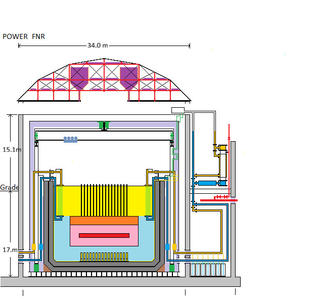
Only 1 of 48 heat transfer loops is fully detailed.
Color Code:
Red - Reactor Core, Steam Main
Pink - Reactor Blanket
Orange- Fuel Tube Plenum
Gold- Warmer NaK pipe
Yellow- hot sodium, hydraulic sodium tube, hydraulic lifter
Light Green - Intermediate Heat Exchange tubes
Dark Green - Hot wall thermal brake support, polar gantry bearings,
Light Purple - Fiber Ceramic Insulation
Dark Purple - NaCl Reservoir
Light Blue- cool sodium
Dark Blue - Cooler NaK Pipe
Light Gray - Concrete
Dark Gray - Fire Brick
Black - Steel Outline
PRACTICAL FNR DESIGN:
A practical FNR has the following additional features:
1) The fuel tubes are spaced so as to ensure that R > 0 can be achieved while also allowing natural circulation of theliquid sodium coolant;
2)The fuel bundle geometry is chosen to minimize the effects of core region fuel tube swelling;
3) The fuel rod geometry is chosen to surround the core fuel region with a neutron absorbing blanket fuel region for breeding fertile fuel into fissile fuel;
4) Each fuel tube contains a plenum space for collecting inert gas fission products;
5) The fuel assembly is surrounded by a 3 m thickness of sodium to absorb leakage neutrons that otherwise would neutron activate the intermediate heat exchange bundles and the sodium pool structure.
6) Below the fuel assembly are piston type hydraulic actuators that set the position of the movable fuel bundles used to provide gross control of the fuel assembly reactivity.
7) Above the movable fuel bundles are vertical indicator tubes which show the actual positions of the movable fuel bundles.
8) At the perimeter of the liquid sodium pool are immersed intermediate heat exchange bundles containing flowing NaK that are used to extract heat from the liquid sodium pool.
FNR NUCLEAR POWER PLANT (NPP) DESIGN CONSIDERATIONS:
The main appeal of an FNR with fuel reprocessing is that it is 100X to 200X more efficient in use of natural uranium than is a water cooled reactor. A companion issue is that sodium cooled FNRs operaate at low liquid metal pressures, potentially allowing such FNRs to be installed at urban sites.
Demonstration FNRs have been built since the early 1960s. FNRs cannot be directly cooled by water because the hydrogen in the water absorbs the fast neutron energy before sufficient fast neutron fission can occur. In a FNR the reactor coolant must be a substance that has sufficiently high atomic weight, is liquid over the reactor operating temperature range and has a low neutron absorption cross section. The possible coolant choices are certain liquid metals, certain metal eutectics and certain molten salts.
Molten salts have the disadvantages that their melting point is relatively high, their corrosion chemistry is complex and their fuel reprocessing chemistry is complex.
From a neutronic property perspective a lead-bismuth eutectic is likely the best FNR coolant. However, lead is a neuro-toxin and neutron excited bismuth decays into polonium, which is one of the most toxic materials known to mankind. Hence, from a workplace health and safety perspective, a lead-bismuth eutectic in not an acceptable FNR coolant choice.
The coolants used in most practical liquid metal cooled FNRs are either liquid sodium or liquid sodium-potassium eutectic (NaK). Sodium has a lower fast neutron absorption cross section than NaK, but Na melts at 98 degrees C whereas NaK is liquid down to below room temperature. In the reactor design discussed herein the reactor coolant is sodium and the intermediate coolant is NaK.
As compared to water, sodium as a reactor coolant has several disadvantages:
a) Sodium melts at about 99 degrees C;
b)Above 200 degrees C sodium spontaneously burns in air;
c) Sodium chemically reacts violently with water yielding heat and hydrogen gas, which spontaneously ignites in air. In a reactor environment the sodium must be covered with an inert gas, usually argon. Sodium cooled reactors are not suitable for marine applications.
d) In a neutron flux part of the sodium (Na-23) becomes Na-24 which has a half life of about 15 hours. That compares to neutron excited O-18 in water that in a neutron flux becomes O-19 that beta decays with a half life of 29 seconds to stable F-19. Hence neutron excited water becomes safe after about 5 minutes whereas neutron excited Na takes at least a week to become safe.
e) The heat capacity of NaK is small as compared to water. The temperature difference across a NaK heat transport loop is typically four times the temperature difference for a similar sized water based heat transport loop. That large temperature difference can potentially cause large thermal stresses which must be carefuly managed.
f) Hence, to maintain a high capacity factor a sodium cooled FNR needs many independent heat transport loops, such that some can be shut down and serviced without shutting down the FNR. Otherwise the sodium cooled NPP will likely financally fail due to operating at a low a capacity factor caused by combined thermal stress triggered leaks and larger shutdown times for service.
g)It is essential to do all necessary to ensure that if the sodium ever burns or reacts with water producing Na2O or NaOH that these compounds be safely contained for at least a week.
h) The argon over the sodium pool contains radioactive sodium vapor. Hence the sodium pool should be surrounded by reliable nested gas tight containment enclosures.
i) Sooner or later an intermediate heat exchange bundle will develop a micro leak. This leak can easily be detected with a radiation sensing device if the NaK pressure is less than the Na pressure such that Na leaks into the Nak, not vice versa. Hence a vacuum should be maintained over each NaK loop to lower the NaK liquid pressure in the intermediate heat exchange bundle.
j)Sooner or later a steam generator tube will fail causing water to jet into the NaK. The system must safely manage the resulting steam and hydrogen that will be instantaneously injected into the NaK loop and the accompanying liquid pressure pulse.
k) The initial fissile fuel concentration in a FNR is typically 5X the initial fissile fuel concentration in a light water cooled reactor. That initial fissile fuel concentration requirement has initial capital cost consequences.
FNR NUCLEAR POWER PLANT (NPP) FACILITY:
The web page titled: FNR Facility briefly describes the appearance of a FNR based nuclear power plant (NPP) that can be safely located in the middle of a population center of about 100,000 people to provide up to 300 MWe of electricity and up to 700 MWt of low temperature district heat.
Alternatively this same facility can provide up to 1000 MWt of high grade steam (10 Pa at 400 degrees C).
A FNR NPP consists of three major systems:
a) The FNR and its enclosures;
b) The heat transport system which extracts heat from the FNR at a controlled rate and uses that thermal energy to form 10 MPa steam at 400 degrees C with a saturation temperature of about 320 degrees C;
c) A steam turbogenerator system with turbine bypass, associated condenser, heat sink, condensate injection pump, condensate heater, and related electrical switchgear.
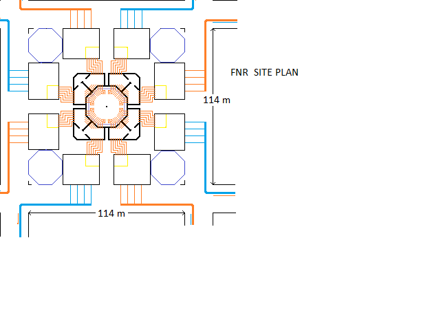
Not including perimeter roads and nearby human support facilities, the FNR NPP above grade structures fully occupy one city block (a space 114 m X 114 m). The NPP footprint consists of a 52 m diameter central nuclear island with a 34 m diameter central dome shaped roof. The nuclear island is separated by 10 m wide laneways from 12 surrounding structures. These structure heights vary from 20 m to 50 m above grade.
The sodium pool is centrally located, mostly below grade, in the nuclear island. Normally there is no personnel access to the sodium pool space because it is very hot, there is gamma radiation, sodium vapor and no oxygen to breath. However, during reactor operation one can view the top of the sodium pool either through a thick window or via a video camera.
When the FNR is off and after the sodium pool has cooled to about 120 degrees C and the Na-24 gamma ray emission has subsided, fuel bundles and equipment can be moved in and out of the sodium pool space via four airlocks.
The sodium pool is circular, 20 m inside diameter X 15 m deep, is located in the middle of a 26 m diameter cylindrical space. The liquid sodium surface is about 1 m below the pool deck and the ceiling is about 10 m above the pool deck. The liquid sodium is a low density metal that melts just below the boiling point of water at sea level.
In the middle of the sodium pool there is a 10.4 m diameter array of 464 vertical indicator tubes which, during normal reactor operation, project about 0.9 m above the sodium surface. These indicator tubes provide the actual elevations of the reactor's movable fuel bundles and the local sodium temperature to ceiling mounted reactor monitoring systems. In the event of a ceiling or gantry crane collapse the indicator tubes also have a role in emergency safety shutdown.
Close examination of the sodium pool surface reveals a slight liquid sodium ripple because, when the reactor is producing power, natural circulation causes liquid sodium to rise in the center of the sodium pool and to sink near the sodium pool walls.
If the overhead lighting is extinguished, during normal reactor operation there is a faint near infrared glow, because normally the exposed surfaces of the sodium pool and the sodium pool enclosure are in the temperature range 460 to 500 degrees C.
There are 96 X 16 inch dia radial pipes which cross horizontally over the pool deck and connect to the intermediate heat exchange bundles immersed in the sodium pool. These pipes contain a sodium-potassium alloy (NaK) which conveys heat captured by the intermediate heat exchange bundles to steam generators located in the heat exchange galleries located adjacent to but outside the reactor space.
High pressure (10 MPa) high temperature (400 degrees C) steam conveys heat from the steam generators , under the ring lane to nearby turbogenerator barns. The turbogenerator related equipment converts about 30% of the transported heat into electricity and rejects the balance of the transported heat to a heat sink or district heating pipes. Note that the NaK pipes and steam pipes are mounted so that they can thermally expand and contract without causing significant material stress.
At the pool deck level are four radial trays that are used, in combination with the air locks and an overhead polar gantry crane, to move fuel bundles and replacement intermediate heat exchange bundles in and out of the reactor space. The inner air lock doors are located behind removable portions of the insulated side walls.
The nuclear island is very quiet. In most industrial installations there is a lot of background noise. However, inside the FNR nuclear island there are few mechanical moving parts. Within this building liquids move by natural circulation, by smooth induction pumping or by differential gas pressure.
If you listen carefully you can hear fan or blower noise from the ventilation system. The sodium pool and the various radial pipes are hot. In spite of good thermal insulation part of that heat leaks into the service space, so to remove heat from the service space forced air ventilation with closed circuit cooling is used.
In simple language the FNR passively supplies nuclear heat at a variable rate from 100 MWt to 1000 MWt. Near the sodium pool perimeter heat is extracted from 460 degree C surface sodium by cooler NaK flowing through the intermediate heat exchange bundles. This heat extraction cools the adjacent sodium causing it to sink. This cooler sodium sinking establishes a natural circulation flow pattern in the sodium pool in which sodium sinks near the pool perimeter and rises near the pool center. As a result of this natural circulation the temperature at the pool bottom center can fall to as low as 400 degrees C. The rate of heat generation by the nuclear process is proportional to the temperature difference between the fuel assembly bottom and the fuel assembly top which sets the sodium natural circulation flow rate. Note that about half of the circulating sodium bypasses the intermediate heat exchange bundles.
In principle the faster that the pumped NaK removes heat from the liquid sodium the more electric power can be generated.
If the NaK flow stops the cooling of the sodium stops. Hence the sodium natural circulation flow stops which causes the nuclear fission to stop. After prolonged operation at 1000 MWt if the fission process is stopped the reactor continues to produce heat at about 80 MWt due to emission of fission product decay heat.
The design maximum power capacity of the FNR NPP is 300 MWe electrical, 700 MWt low grade thermal or 1000 MWt high grade thermal. In practical application during the summer most of the low grade heat rejected by electricity generation is discarded. However, in the winter up to 700 MWt of low grade heat is available for district heating. Generally this low grade heat should be used as the heat source for high COP water source heat pumps.
Note that the FNR sodium coolant discharge temperature is fixed at 460 degees C and the FNR thermal power output increases with increasing NaK flow. Induction pumps set the operating NaK flow rate. The heat transport system design prevents the operating sodium temperature at the bottom of the fuel tubes falling below 400 degrees C. This thermal power constraint limits the maximum heat flux through the FNR fuel tubes, which prevents metallic nuclear fuel center line melting and protects the fuel tubes from excessive heat and neutron flux.
A FNR has the virtue of rugged simplicity. However, a lot of work has gone into designing the FNR to safely tolerate both peripheral equipment failures and extreme events such as earthquakes, tornados, airplane impacts and terrorist attacks.
A practical FNR must be maintainable. Eventually the nuclear fuel will be consumed and it will be necessary to shuffle and/or recycle the nuclear fuel. If air leaks into the reactor space over time the oxygen and water vapor in the air will react with the liquid sodium forming a NaOH sludge with a melting point of 318 degrees C that should be continuously filtered out of the liquid sodium.
Changes in thermal load cause thermal expansion and contraction of the steam generators, NaK pipes and heat exchange bundles which cause long term wear. Internal pipe scouring causes further long term wear, eventually leading to equipment repair or replacement. Any suspended particulates in the NaK heat transport fluids will aggravate long term scouring of the insides of pipes, fittings and heat exchange bundles. Hence, in spite of the apparent equipment simplicity, there are important ongoing maintenance considerations related to fluid cleanliness.
Note that there are 48 heat transport circuits and up to 8 turbogenerators, so various combinations of them can be shut down for service without impacting the performance of the remainder. However, exceot during planned reactor shutdowns, the combined turbogenerator output should always exceed the induction pump load necessary for decay heat extraction.
Most of the system ongoing maintenance is non-nuclear in nature and is related to the heat transport system, steam turbines, condensers, cooling towers, electricity generators, cooling water pumps, injection water pumps and other non-nuclear electrical and mechanical equipment.
Normally the nuclear island can operate for months with minimal maintenance attention. The reactor power can be remotely adjusted by changing the induction pump set NaK flow rate. If anything in a heat transport circuit fails the simple solution is to turn off the corresponding induction pump and drain its NaK to its dump tanks until such time as competent maintenance personnel can attend to the problem. There is sufficient equipment redundancy to permit the FNR NPP to continue operation at slightly reduced power with some of its heat transport circuits and/or some of its turbogenerators out of service.
The liquid sodium pool operates at atmospheric pressure with argon cover gas. Unlike water cooled reactors there is nothing to blow up. If the induction pumps are turned off this reactor will passively default to its setpoint temperature. By venting the steam generators there should be enough NaK natural circulation to expel decay heat.
The other main safety concern is fire prevention by continuous exclusion of both air and water from the sodium pool space.
SAFETY SHUTDOWN MECHANISMS:
A FNR is shut down by changing its fissile fuel geometry to reduce its reactivity.
A FNR has five independent shutdown mechanisms. One mechanism is passive thermal expansion which is used for normal operating temperature control. Two shutdown mechanisms are also used for adjustment of the reactor operating temperature To and for planned reactor shutdowns. Two are intended only for emergencies involving an unplanned overhead collapse or a sudden unplanned fuel geometry change.
INTRODUCTORY GLOSSARY OF TERMS:
FNR: Fast Neutron Reactor;
NPP Nuclear Power Plant;
Fission: Splitting of an atomic nucleus, usually triggered by neutron absorption;
Fissile Fuels: Materials that readily liberate nuclear energy via neutron capture induced fission;
Fission Thermal Power: Rate of heat generation caused by fission reactions;
Reactivity R: A mathematical parameter which indicates the rate of change number of free neutrons in a nuclear reactor and hence fractional rate of loss or gain in fission thermal power;
Power Reactor: A nuclear reactor intended for producing electricity and/or heat;
Sodium: A highly thermally conductive highly reactive metal that melts at 98 degrees C;
Sodium Pool: A pool of liquid sodium about 20 m diameter X 15 m deep which captures both the heat and radiation emitted by centrally contained nuclear fuel;
Indicator Tubes: Vertical metal tubes which project above the surface of the liquid sodium pool to convey movable fuel bundle position and local sodium temperature information to ceiling mounted electronic monitoring systems;
Hollow Stainless Steel Spheres: Buoyant stainless steel balls about 20 cm in diameter that float on the surface of the liquid sodium to reduce its exposed surface area and to assist in sodium fire asphixiation;
NaK: An alloy of the metals sodium and potassium that is liquid from below room temperature up to over 700 degrees C;
Intermediate heat exchange bundle: A bundle of metal tubes that transfers heat from the hot liquid sodium to slightly cooler but fully isolated flowing NaK;
Induction Pump: A non-contact electromagnetic pump type used for circulation of NaK;
1000 MWt: One thousand million watts thermal (sufficient thermal power to meet all the power requirements of about 100,000 North American people)
This web page last updated February 17, 2026.
| Home | Energy | Nuclear | Electricity | Climate Change | Lighting Control | Contacts | Links |
|---|